
OLED I2C DISPLAY ARDUINO/NODEMCU TUTORIAL
The very first program you write when you start learning a
new programming language is: "Hello World!".
The program itself does nothing more than printing a “Hello World” text on the screen.
So, how do we get our Arduino to display the "Hello World!"?
In this video, I will be showing you how to get started with the small 0.91 (128x32) and 0.96 (128x64) I2C OLED displays.
There are 100s of tutorials on the web explaining the same thing in different ways, but I couldn't find one that tells me all about the OLED display and how to use it in different scenarios. It took me some time to work it all out. So, I thought I should create a tutorial on what I have learned and combine all the features and ways the OLED displays can be used in our projects.
Step 1: Things We Are Going to Learn Today
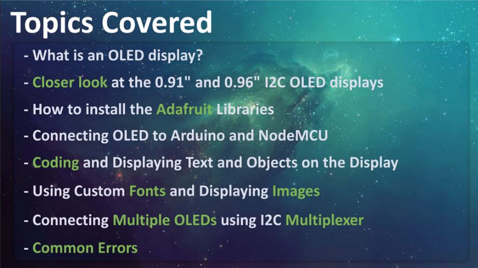
In this video we will be talking about:
- What is an OLED display?
- Then we will have a closer look at the 0.91 (128x32) and 0.96 (128x64) I2C OLED displays
- Next we will talk about installing the Adafruit Library to your Arduino IDE
- Then we will connect NodeMCU and Arduino to an OLED display
- Next we will have a look at the code and display some graphics and text on it
- We will also talk about applying Custom Fonts and displaying Images
- Then we will connect Multiple OLEDs to a micro-controller using I2C Multiplexer
- Finally, we will talk about few common errors people make while using the OLED displays
Step 2: Hardware Requirement

For this tutorial we need:
- A Breadboard
- A 0.91" (128x32) and 0.96" (128x64) I2C OLED displays
- Arduino UNO/NANO (whatever is handy)
- NodeMCU
- TCA9548A I2C multiplexer
- Few Connecting Cables
- and a USB cable to upload the code
Step 3: What Is an OLED Display?

OLED or organic light-emitting diode is a light-emitting diode (LED) in which the emissive electroluminescent layer is a film of organic compound (millions of small LED lights) that emits light in response to an electric current.
OLEDs are used to create digital displays in devices such as television screens, computer monitors, portable systems such as mobile phones, hand-held game consoles and PDAs. An OLED display works without a backlight because it emits visible light.

There are many types of OLED displays available in the market based on their
- Sizes
- Color
- Brands
- Protocol
- SPI (Serial Peripheral Interface) or I2C
- Passive-matrix (PMOLED) or active-matrix (AMOLED) control scheme
In this tutorial, I am going to talk about connecting the blue color 0.91 (128x32 OLED) and 0.96 (128x64 OLED) I2C OLDE displays to an Arduino NANO and NodeMCU. I2C bus technology uses only 2 pins of the MCU so we have heaps available for other sensors.
Step 4: Closer Look

Lets have a closer at these two displays.
At the back of these displays there are heaps of SMD capacitors and resistors soldered on-board; but, since its an I2C device we only care about these 2 pins (SCL and SDA)
The display connects to Arduino using only four wires – two for power (VCC and GND) and two for data (serial clock SCL and serial data SDA), making the wiring very simple. The data connection is I2C (I²C, IIC or Inter-Integrated Circuit) and this interface is also called TWI (Two Wire Interface).
- The on-board pins can be in different order, so always triple check before hooking it up to your project.
- Operation voltage is between 3v to 5v but, it is best to use the guidance from the manufacturer's datasheet.
- Sometimes we need to use 2 displays in our projects. So, how can we achieve this?
The trick is to have a configurable address on your display. This unit has a configurable address between 0x78 and 0x7A. Just by unsoldering the 0Ohm resistor from one side and hoking it up to the other side or just by putting a global solder we can change the address. We will talk about it in depth when we hook up multiple displays to an Arduino in the later section of this tutorial.
In picture these displays look very big. But, practically speaking they are tiny. They are made of 128 x 32/64 individual OLED pixels and do not require any back-light. Just have a look at this and see how small it is. Even though they are small they can be very useful in any electronic projects.
Step 5: Library

There are several libraries available to control these displays. In past I have used the "u8glib library" but I find the AdaFruit library very easy to understand and use in our projects. So, I am going to use the AdaFruit library in this tutorial.
To control the OLED display you’ll need the "adafruit_GFX.h" library and the "adafruit_SSD1306.h" library.
There are two ways you can download and install the library to your Arduino IDE.
Method 1
Go to the "Library manager" and search "adafruit_SSD1306" and "adafruit_gfx"
Select the latest version and hit the Install button.
Once installed you can use these libraries in your program.
Method 2
These two libraries can be also be downloaded from github (you need both):
The display library: https://github.com/adafruit/Adafruit_SSD1306
The GFX library: https://github.com/adafruit/Adafruit-GFX-Library
Once downloaded, copy the Adafruit_SSD1306-master folder from the downloaded zipped file into the Arduino libraries folder. This folder is usually found at Documents > Arduino > libraries on Windows systems. On Linux it is usually found at home folder > Arduino > libraries. Finally in the Arduino library folder, rename the Adafruit_SSD1306-master folder to Adafruit_SSD1306. Even if you don’t rename that’s fine.
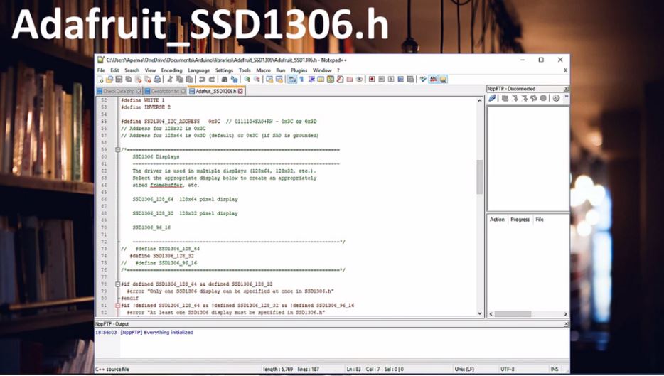
Now, lets have a look at the "Adafruit_SSD1306.h"
Two things we need to know in this library:
1. If you want to use the smaller display use the default 128_32 otherwise for the bigger display comment the 128_32 and uncomment the 128_64
2. If you have soldered the 0x7A Address on the board (which we will talk about later) then use the 7 bit 0x3D address for the bigger displays, otherwise use the default 0x3C address. For the smaller displays the address is 0x3C.
Step 6: Wiring 128 X 64/32 OLEDs

Lets start by connecting the NodeMCU to the display.
The first and most important thing to note is that some of the displays may have the GND and VCC power pins swapped around. Check your display to make sure that it is the same as the image. If the pins are swapped, make sure to change the connections to the Arduino or NodeMCU.
- NodeMCU OLED Wiring
OLED VCC – NodeMCU 3.3V
OLED GND – NodeMCU GND
OLED SCL – NodeMCU D1
OLED SDA – NodeMCU D2
- Arduino Uno OLED Wiring
OLED VCC – Arduino 5V
OLED GND – Arduino GND
OLED SCL – Arduino Uno A5
OLED SDA – Arduino Uno A4
- Arduino MEGA 2560 OLED Wiring
OLED VCC – Arduino 5V
OLED GND – Arduino GND
OLED SCL – Arduino MEGA 2560 pin 21
OLED SDA – Arduino MEGA 2560 pin 20
Step 7: Code

Adafruit library comes with really good examples for both
128x32 and 128x64 displays.
The Library is located under File > Examples > Adafruit SSD1306 > and then the display type in the Arduino IDE.
We are going to use the 128x32 I2C example and will modify it to work with both 128x64 and 128x32 displays fist by hooking it up to an Arduino and then to a NodeMCU board.
The code starts by including both the Adafruit libraries. In this tutorial I am going to stress on only those parts of the code which are necessary for us to load on both boards and displays. If you want to know more about the code please drop a comment on my blog or in the comments section below and I endeavour to get back to you.
- First we are going to load the code to an Arduino Nano connected to a 128x32 display.
We can use the code as is without any modifications.
128x32 uses 0x3C address so this bit looks all good here, lets double check the header library, yes its also using the 0x3C address and the display type is 128x32.
- Now lets connect the 128x64 display. As we know it uses the 0x3C address by default so we don't need to update the address in either the code or the library.
We just need we need to comment the 128_32 and uncomment the 128_64 in the header library and change the LCDHEIGHT to 64 in our code.
- Now to run the same code on a NodeMCU we need to change one more line in our code.
The "#define OLED_RESET 4" > "#define OLED_RESET LED_BUILTIN" rest of the code is same as Arduino
Pretty much to display anything we first need to clear the previous screen using
display.clearDisplay(); // Clear the buffer
Then draw the object
testdrawline(); // Draw a line
Show it on the hardware
display.display(); // Make them visible on the display hardware!
Wait for some time before displaying the next item.
delay(2000); // Wait for 2 seconds
In this example we are displaying few items like text, lines, circles, scrolling text, triangles and more. Go ahead and use your imagination and display whatever you want on these tiny displays.
Attachments

Step 8: Customizing Text & Adding Images

Sometimes your code needs to display custom fonts and images. If you are very good in bit mapping then you just need to create a byte arrays by turning on or off the tiny LEDs of the display to create custom fonts and images.
However, I am not very good in doing these mappings and don't want to spend hours creating the bit map tables.
So, what are my options? I generally use two websites to generate custom fonts and images. The links are provided in the description below.
Custom Fonts
Go to the font converter website, select the font family, style, size, Library Version as "Adafruit GFX Font" and then hit the "Create" button. On the right hand side of this page you can see how your font is going to look like on the actual display.
Based on your selection the webpage generates the fonts header file. Create a file called "modified_font.h" in the same folder where your code is and copy and save the generated code into it. Then you just need to include the header file in your code to use the custom font.
#include "modified_font.h"
Then, you just need to set the font before displaying the text to apply the custom font to it.
display.setFont(&Your_Fonts_Name);
You can get the name of the font from the header file you just added to your project. Thats it, easy.
Memory is always a concern while using custom fonts, so always consider the bytes that will be consumed by the memory. Just remember Arduino UNO has only 32K of memory.
Custom Images
To display a bitmap image on your screen you first need to create a 128 x 64/32 sized image.
I am using the good old "MS Paint" to create a 128 x 64 bitmap image which I will then upload to this image converter website. The website converts images into byte-strings, which can be used with Arduino and OLED displays.
Start by uploading the image to the website. Then put a check on the "Invert image colors" check-box and change the "Output code format" to "Arduino Code" next select the orientation and hit the "Generate Code" button to generate the byte array. The "Preview" section shows you how your image will look like on the actual display.
I have included the code along with this tutorial which you can use to display your images. You just need to replace the array in my code with the one you just generated and then load it to your Arduino.

No comments