In my last tutorial I created a NodeMCU based Duino Coin Miner. It is an awesome little miner that sits on my desk and mines few cents a day.
However, adding these miners to my home network choked my WiFi router. Home Appliances and Smart Devices connected to the router constantly started dropping off. To my understanding, most of the wireless routers and access points can support upto 250 devices connected at once. So, what's happening here?
To clarify my doubts I called my ISP. The answer they gave was absolutely shocking. "ONLY 30 devices can successfully connect and exchange data via their router at any given time". Bloody hell!!
So, to overcome this limitation I added another router to the network to scale up the load.
But, I was not happy with this solution. So, I did a bit of research and found this "NRF24L01 RF Transceiver Module" which I can use to create a mesh of wirelessly connected microcontrollers.
In this tutorial, I am going to show you guys how to use this transceiver module to add wireless communication between two or more Arduino boards. I will be using this module for many of my upcoming home automation projects. Bang Problem solved..
Early Bird Prize Winner at ElectronicWings: https://www.electronicwings.com/users/AshishAdhikari/projects/2045/nrf24l01-tutorial---arduino-wireless-communication
Sponsors
This video is sponsored by PCBWay.

PCBway: only $5 for 10 pcbs from https://www.pcbway.com/?from=CZcouple
PCBWay specialize in manufacturing of very high quality, low-volume, colored PCBs at a very budgetary price. In addition to the standard PCBs, you can also order Advanced PCBs, Aluminum PCBs, FPC/Rigid-flex PCBs. They also provide PCB assembly and other related service which can meet your needs to the greatest extent.
The ordering process from PCBWay is very easy. Once I had my design ready, I just had to upload the gerber file to the PCBWay's website and select the type, color and any other customization that I want and then just send it for fabrication.
For my project, I choose the black color. PCBWay ships from china to most of the countries of the world within 3 to 7 business days. Talking about the quality, its absolutely mind-blowing.
What is a NRF24L01 RF Transceiver Module?

So far, I have always used WiFi for wireless communication between microcontrollers. While this is easy enough to do, it is not exactly suitable for battery operated nodes. WiFi modules consume a lot of current when transmitting data plus they also have a slight delay when initiating the transmission as the module has to first connect to the WiFi network.
After getting crippled by the abilities of my wireless router, I found this cheap, very popular and widely used "RF Transceiver Module" which you can hook up to any microcontroller (MCU). This module is called a RF transceiver because a single module can work both as a transmitter and a receiver.
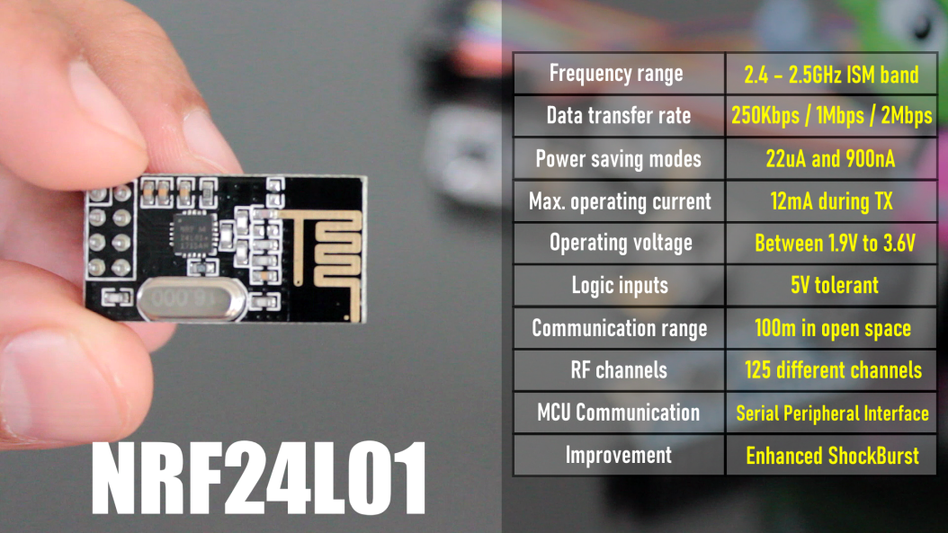
- The module operates at a frequency of 2.4GHz, which is one of the ISM band which means it is open to use in most of the countries around the World.
- Data transfer rate is between 250kbps to 2Mbps baud.
- Power consumption? This module is designed for ultra low power wireless applications. It has 2 power saving modes operating at 22uA Standby-I mode and 900nA in power down mode - which makes these modules suitable for battery operated nodes. The high air data rate combined with two power saving modes makes the nRF24L01 module very suitable for ultra low power designs. The power consumption of this module is just around 12 milliamps during transmission (TX) which is even lower than a single led.
- Operating voltage is between 1.9V to 3.6V. All other pins on this board are 5V tolerant making it easy to connect to an Arduino without using a logic level converter. It has an integrated (on chip) voltage regulator.
- The Range of this module as per its datasheet is 100m but it works up to 50 to 60 meters in real world conditions.
- The module has 125 independent RF channels giving the possibility to have a network of "125 independently working modems" in one place. Each channel can have up to "6 addresses or 6 data pipes" or in other words, each unit can communicate with up to 6 other units at the same time (1:6 star networks).
- The module is configured and operated through a Serial Peripheral Interface (SPI).
- It uses Enhanced ShockBurst™ for automatic packet assembly and timing, automatic acknowledgement and retransmission of packets. Enhanced ShockBurst™ enables the implementation of ultra low power, high performance communication with low cost host microcontrollers. The features enable significant improvements of power efficiency for bi-directional and uni-directional systems, without adding complexity on the host controller side.

The module used in this video has an in-built PCB antenna making it compact. However, you can also buy a variant that supports an external antenna allowing much higher range of about 1000M in line of sight.
nRF24L01 Pinout

Now, lets have a look at the pinouts and specifications of the NRF24L01 module:
- GND: is the Ground Pin. It is placed inside a square for easy identification.
- VCC: supplies power to the module. Voltage can range from 1.9v to 3.9v. So, you can connect it directly to the 3.3V pin of our Arduino. Remember connecting it to a 5V pin will likely destroy your nRF24L01+ module!
- CE: (Chip Enable) is an active-HIGH pin. When selected the module will either transmit or receive, depending upon which mode it is currently in.
- CSN: (Chip Select Not) is an active-LOW pin and is normally kept HIGH. When this pin goes low, the module begins listening on its SPI port for data and processes it accordingly.
- SCK: (Serial Clock) it accepts clock pulses provided by the SPI bus Master.
- MOSI: (Master Out Slave In) It is SPI input to the module. It is used to receive data from the microcontroller.
- MISO: (Master In Slave Out) It is SPI output from the module. It is used to send data to the microcontroller.
- IRQ: It is the interrupt pin that alerts the master when new data is available to process.
Setup and Schematic

In order to get this working, we need two such NRF24L01 Modules and two Arduino Boards. For this tutorial I am going to use 2 Arduino Nanos.
Just remember, we cannot use a breadboard with these modules because the pin spacing on these modules are not enough to place it in the middle and if you place it anywhere else, then you will end up shorting the pins. This means that you will either have to solder the wires directly to the modules or use some sort of jumper cables.

The connection is exactly the same on both the transmitter and receiver end.
Connect the GND pin to -ve and VCC pin to 3.3v pin of Arduino. The signals generated by these modules are very sensitive to power supply noises. So, adding a decoupling capacitor (anything from 10uF to 100uF) across the power supply line is always a very good idea.
Then connect the CSN pin to D8, CE to D9, MOSI to D11, MISO to D12, and SCK to D13 pin of the Arduino.
Since the nRF24L01+ module requires a lot of data transfer, it will give the best performance when connected to the hardware SPI pins on the microcontroller. Note that each Arduino board has different SPI pins that must be connected accordingly. Have a look at the table onscreen for quick understanding.
Library Used

For this tutorial I am going to use the "TMRh20/RF24" OSI Layer-2 driver for nRF24L01 on Arduino & Raspberry Pi/Linux Devices. You can download the library from the link provided in the description below: https://github.com/tmrh20/RF24/.
Code 1 - Sending Text

In my first example, I am going to send a character array from one module to the other. Using a split screen I am going to demonstrate this example. On my left is the Transmitter Code and on my right is the Receiver Code.
Lets start by including the "SPI library" followed by the "RF modules library" downloaded from github in the code.
Then we are creating a RF24 object by passing the CSN and CE as the two arguments to the radio() function.
Next, we are creating an array of the addresses that the modules will use to communicate amongst themselves. The address can literally be anything, however, it has to be the "same" on both the transmitter and the receiver modules. This is how the RF modules know who they have to communicate with.
In the setup section we first initialize the radio object.
Then, using the radio.openWritingPipe() function we set the address of the transmitter which we will use to send data to the receiver module. On the receiving end we use the radio.openReadingPipe() function with the same address to read the data from the data pipe.
Next we set the power amplifier level. Since the modules in this demo are sitting next to each other, I am using the "Minimum Level".
Next, in the transmitter code we need to tell the module to stop listening using the radio.stopListening() function. This sets the module as a transmitter. On the receiver module we need to start listening using the radio.startListening() function. This sets the module as a receiver.
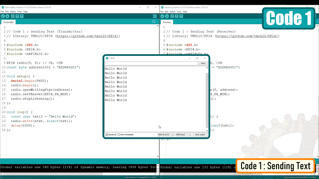
After that, in the loop() section of the transmitter, we send an array of characters using the radio.write() function and on the receiver end we read the array using the radio.read() function and display it on the serial monitor every second.
Code 1: Download
Code 2 - Lighting Up LEDs

In the second example, I am going to light up two LEDs on the receiver-end based on whichever button is pressed on the transmitter-end.

To achieve this I have added 2 LEDs on the receiver end and 2 Push Button switches on the transmitter end.

When Button B1 is pressed the transmitter sends "B1" using the radio.write() function and when Button B2 is pressed the transmitter sends "B2" using the radio.write() function to the receiver module.
The "switch statement" in the receiver code then lights up the corresponding LED based on whichever button was pressed on the transmitter end.
Code 3 - Same Node Acting as TX and RX [Bidirectional Communication)

In my 3rd example I will show you guys how a single node can act as both transmitter and receiver. Just remember you "cannot" send and receive data at the same time. Using the "stopListening()" and "startListening()" functions we will toggle between sending and receiving of data on the data pipes.
What's different here from the previous code is that we are creating two pipes or addresses for the bi-directional communication.
const byte addresses[][10] = {"ADDRESS01", "ADDRESS02"};
In the setup section we need to define both pipes in a way that the sending address of the 1st module is the receiving address of the 2nd module and vice versa the receiving address of the 1st module needs to be the sending address of the 2nd module.
Now in the loop section of the 1st Arduino, we use the radio.stopListening() function to turn the node into a transmitter and send the data using the radio.write() function.
On the receiver end we use the radio.startListening() function to read the incoming data. While there is incoming data (radio.available()) we read it using the radio.read() function. Then we add a bit of delay to the code.
After that, we set the 1st Arduino to receiving mode using the radio.startListening() function and the 2nd Arduino to transmitting mode using the radio.stopListening() function.

The data is then displayed on screen using the Serial Monitor.
Code 3 : Download
Code 4 - Multiple Nodes [Mesh - Multiceiver Network]

The nRF24L01+ has a feature called Multiceiver. It is an abbreviation for Multiple Transmitter Single Receiver. In my 4th example, I am going to show you guys how to connect multiple transmitters to a single receiver.
In a Multiceiver network each RF channel is logically divided into 6 parallel data channels or the data pipes. Each data pipe has its own unique data pipe address. Only one data pipe can receive a packet at a time.
So basically, the primary receiver in the middle is collecting data from 6 different transmitting nodes simultaneously. The primary receiver can stop listening any time and start acting like a transmitter.
This way you can create a mesh of network where each node can act as a repeater. There is a different library "RF24Mesh" you need to use to create this mesh network. Since I don't have that many modules handy at this moment, I am unable to show you guys the working bit of it. However, I will create a 2nd tutorial dedicated just to the mesh network, so stay tuned.
Using Sleep Mode

There is a way to conserve battery by sending the module to sleep mode. Please read through the "pingpair_sleepy" example for more details, I have provided the link in the description below.
Factor Effecting The Transmission

- These modules work very well when the transmitter and receiver are close to each other. If the distance is too big you may lose the communication.
- The signals generated by these modules are very sensitive to power supply noises. Depending upon the amount of noise, the communication rate may vary.
- Setting the maximum output power can also improve the communication range.
- If there’s an obstacle in the line of sight you may see multiple dropouts.
- Reducing the data rate can significantly improve the performance. A speed of 250kbps is more than enough for most of our projects.
- Using an external antenna can also significantly improve the transmission rate.
- Another potential source of noise for RF circuits is WiFi. Especially when someone's network is set on the same channel. Since WiFi mostly uses the lower frequency channels, it is recommended to use the highest 25 channels for your nRF24L01+ modules.
Thanks
Thanks again for checking my post. I hope it helps you.
If you want to support me subscribe to my YouTube Channel: https://www.youtube.com/user/tarantula3
Blog Posts: Visit Website
Video references: Visit Website
DataSheet: Download
Schema
Schema - Sending Text: Download
Schema - Lighting Up LEDs: Download
Code
Code 1 - Sending Text: Download
Code 2 - Lighting Up LEDs: Download
Code 3 - Bidirectional Communication: Download
Libraries Used
TMRh20/RF24 : Visit Website
TMRh20/RF24 : Download
RF24Mesh : Visit Website
pingpair_sleepy : Visit Website
Support My Work
BTC: 1M1PdxVxSTPLoMK91XnvEPksVuAa4J4dDp
LTC: MQFkVkWimYngMwp5SMuSbMP4ADStjysstm
DOGE: DDe7Fws24zf7acZevoT8uERnmisiHwR5st
ETH: 0x939aa4e13ecb4b46663c8017986abc0d204cde60
BAT: 0x939aa4e13ecb4b46663c8017986abc0d204cde60
LBC: bZ8ANEJFsd2MNFfpoxBhtFNPboh7PmD7M2
Thanks, ca again in my next tutorial.
Tags
----
nRF24L01+ Module, Wirelessly Communicate Between Arduinos, NRF24L01 Tutorial, Arduino Wireless Communication, NRF24L01 Arduino Tutorial, How the nRF24L01 Wireless Transceiver Module Works With Arduino, Arduino, wireless communication between microcontrollers, wireless doorbell, RF433, NRF24, nRF24L01 sleep mode, arduino wireless tutorial,Multiceiver Network, Multiceiver, nrf24L01 Multiceiver, radio module,


No comments:
Post a Comment