
This
project features a custom 3D-printed 'Mortal Kombat' trophy shell
paired with a basic NE555 timer circuit in 'astable mode', producing a
smooth 'breathing' LED effect—mimicking the gentle pulse of a living
light.
Watch this video for detailed step by step instructions on
how to build this circuit and to know how this circuit works. You will
discover how to blend retro gaming charm with modern electronics to
create a stunning, attention-grabbing masterpiece.
Video: https://youtu.be/Q4CRfxDFBEk
Sponsors

PCBWay ships from china to most of the countries of the world within 3 to 7 business days. Talking about the quality, its absolutely mind-blowing.

Join The PCBway 11th anniversary event: https://www.pcbway.com/activity/anniversary11th.html
Video Featured On
Instructables: https://www.instructables.com/3D-Printed-Breathing-IC555-LED-Trophy
Hackster: https://www.hackster.io/tarantula3/3d-printed-breathing-ic555-led-trophy-b73e81
Hackaday: https://hackaday.io/project/203370-3d-printed-breathing-ic555-led-trophy
3D Printing

I designed this project's 3D model using Blender. You can either create your own model or download my STL files from platforms like Thingiverse, Printables or Cults3D and then print it using PLA or any other filament of your choice.

3D Printing is a highly addictive hobby! There are so many things you can do using a 3D printer. From designing 3D Models to printing them using the 3D printer has now become my new hobby. I've been a "maker" since I was 10 years old, and have always constructed and made my own stuff. 3D printing for me is a blessing. I am totally lost in the 3D printing heaven.

3D
printing has changed my electronics workshop life forever. Before when I
used to order parts, I always used to wonder if the parts would fit
into my project's resources... but after I got my 3D printer... it
doesn't matter at all, because if it doesn't fit - I can design and
print it myself. The 3D printer was definitely "The Missing Piece" from
my electronics workshop.

To achieve gentle, diffused lighting for this project, I repurposed the semi-transparent plastic from a milk bottle to evenly scatter light and to eliminate glare.

Using Acrylic Colors, I painted the body of the trophy.
The trophy's antique character came to life through strategic dry brushing with earthy browns and muted blues. Once dry, I will superglue the plastic cutout to the back of the front bit.
Components Required
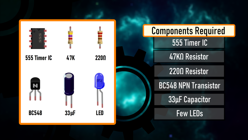
- 555 Timer IC https://s.click.aliexpress.com/e/_oo2U58w
- 47KΩ Resistor https://s.click.aliexpress.com/e/_oDWJZkS
- 220Ω Resistor https://s.click.aliexpress.com/e/_oE27Jk6
- BC548 NPN Transistor https://s.click.aliexpress.com/e/_oEuK8QS
- 33µF Capacitor https://s.click.aliexpress.com/e/_opXdT4E
- Blue LED https://s.click.aliexpress.com/e/_oF9HV9c
Circuit Diagram

How The Circuit Works

- When Pin 2 of the IC detects voltage LESS than 1/3rd of the supply voltage, it turns ON the output on Pin 3.
- And, when Pin 6 detects voltage MORE than 2/3rds of the supply voltage, it turns OFF the output.

threshold pin (Pin6) of the 555 timer IC sense voltages and controls the output at Pin 3.

- The Capacitor attached to the circuit will be in a discharged state immediately after firing up the circuit.
- So, the voltage at Pin 2 will be 0v which is less than 1/3rds of the supply voltage, this will turn ON the output on Pin 3.
- Since Pin 3 is looped back to Pin 2, it will start charging the Capacitor via the 47KΩ resistor.
- At the same time the base current of the transistor also increases causing the LED to slowly "fade-in".
- Once the voltage across the capacitor crosses 2/3rds of the supply voltage, Pin 6 turns OFF the output.
- This causes the capacitor to slowly discharge causing the base current to fall and hence the LED starts "fading-out".
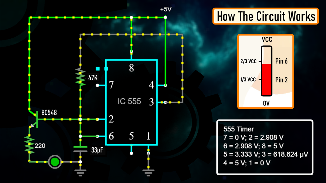
- Once the voltage across the capacitor falls below 1/3rd of the supply voltage, Pin 2 turns ON the output, and the above cycle continues.
Breadboard Demo


The Board


Soldering


Assembling the Trophy


Final Demo

Feel free to leave a feedback or suggestion in the comments if you see any room for improvement.
Thanks
Thanks again for checking my post. I hope it helps you.
If you want to support me subscribe to my YouTube Channel: https://www.youtube.com/@CrazyCoupleDIY
Video: https://youtu.be/Q4CRfxDFBEk
Full Blog Post: View
- What Is Forward Voltage: Visit
- LED Fader Using 555 Timer IC: https://youtu.be/30wGujPnupw
- BTC: 1Hrr83W2zu2hmDcmYqZMhgPQ71oLj5b7v5
- LTC: LPh69qxUqaHKYuFPJVJsNQjpBHWK7hZ9TZ
- DOGE: DEU2Wz3TK95119HMNZv2kpU7PkWbGNs9K3
- ETH: 0xD64fb51C74E0206cB6702aB922C765c68B97dCD4
- BAT: 0x9D9E77cA360b53cD89cc01dC37A5314C0113FFc3
- LBC: bZ8ANEJFsd2MNFfpoxBhtFNPboh7PmD7M2
- COS: bnb136ns6lfw4zs5hg4n85vdthaad7hq5m4gtkgf23 Memo: 572187879
- BNB: 0xD64fb51C74E0206cB6702aB922C765c68B97dCD4
- MATIC: 0xD64fb51C74E0206cB6702aB922C765c68B97dCD4
Tags
----
astable mode,Arduino Mortal Kombat Badge,Retro Gaming Badge,Fighting Game PCB,Mortal Kombat Badge,DIY PCB Badge,Game Mode Badge,3d printing,elegoo,pcbway,PCB badge,3d trophy,PCB V-Scoring,3D printer,retro gaming,pcbway,
Rumble: https://rumble.com/v6v8qnf-3d-printed-breathing-ic555-led-trophy.html
Odysee: https://odysee.com/@Arduino:7/3D-Printed-Breathing-IC555-LED-Trophy:8

No comments