Intro
Walkie-talkie using Arduino, humm.. sounds interesting isn't it?
Alright, lets spend some time today and design and understand this fairly simple circuit, and lets find out how our expectations are challenged by the reality.
Sponsors
This video is sponsored by PCBWay.

PCBway: only $5 for 10 pcbs from https://www.pcbway.com/?from=CZcouple
PCBWay specialize in manufacturing of very high quality, low-volume, colored PCBs at a very budgetary price. In addition to the standard PCBs, you can also order Advanced PCBs, Aluminum PCBs, FPC/Rigid-flex PCBs. They also provide PCB assembly and other related service which can meet your needs to the greatest extent.
PCBWay ships from china to most of the countries of the world within 3 to 7 business days. Talking about the quality, its absolutely mind-blowing.
Story
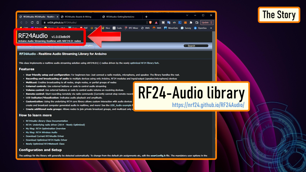
While compiling data for my tutorial on "nRF24L01 Module" (All About nRF24L01 Modules) I found this easy to use RF24-Audio library.

This library has all the basic functionalities that you need to make a DIY walkie-talkie. The sketch is very simple, and I had all the components required to assemble this on a breadboard.

To motivate me even further, I found tons of video tutorials of people making this "super cheap gadget" with "crystal clear voice" transmitted over "1km to 2km of range". Humm, sounds a bit doggy but I still wanted to give it a shot.
This audio library works on top of the RF24 library.
Logic

Lets start by looking at the schematic of this circuit and lets also find out the components required to assemble this circuit.
Before going into much details lets understand the basic requirements of this circuit.
To transmit and receive data from one unit to the other we need some sort of transceiver module and a MCU to process the data.
We need some sort of device/module to capture our voice, and a device/module to convert the sound waves received in the form of electrical signal and relay it as an audible sound wave.
To start the transmission we need a push button and a LED indicator which lights up when the transmission begins. Similarly, at the receiving end we need a LED indicator that lights up when the unit starts receiving data.
Schematic

Alright, now lets replace our logic with the electronic components.
The heart of this circuit is an Arduino Nano.
The voice is transmitted from one unit to the other using a nRF24L01 Transceiver Modules.
Using a Microphone Module connected to the A0 pin of the Arduino, I am going to capture my voice.
And, using a 8ohm 0.5W speaker, connected to the D9 and D10 pin of the Arduino I am going to output the voice received by this circuit.
To initiate the transfer I am using a push button switch connected to the A1 pin of the Arduino.
The Red LED connected to the pushbutton lights up, when we press the button to transmit data.
The Green LED connected to the D6 pin of the Arduino lights up when the unit starts receiving data.
We also need to add a large decoupling capacitor anything from 470uF upwards on the 3.3V line to filter out voltage spikes and to provide enough power to the IC to keep the voltage stable.
You may also need to provide additional power to the nRF24 module using a 3.3V voltage regulator.
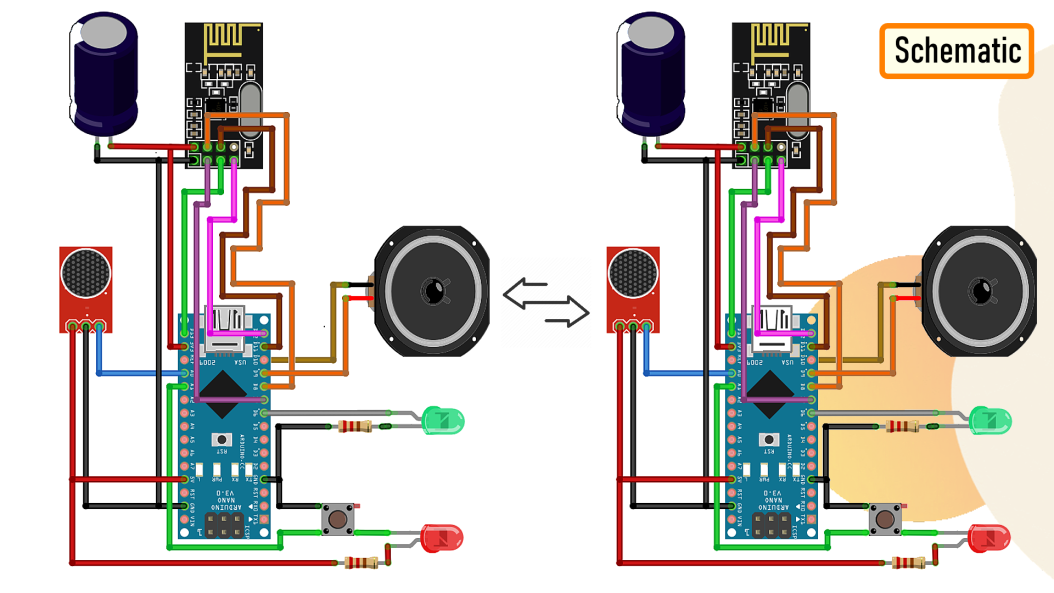
To transmit and receive data, we need exact copies of this module at both transmitting and receiving ends.
The Code

Now lets have a look at the code.
Unless you want to do something super funky, just go ahead and upload the "Minimal" code provided with the RF24Audio library to both the Arduino's present at the transmitting and receiving ends.
The code works perfectly fine with the circuit diagram we discussed in the previous section.

If you want to change any of the pin combinations, then you need to edit the "userConfig.h" file which you can find inside the Arduino libraries folder.
That's all you have to do to get this all up and running.
Demo

Alright, now the interesting bit. Lets go ahead and test this super cheap Arduino based walkie-talkie.
As you can hear, the sound quality is a total disaster.
I tried a few things like altering the sampling rate, altering the transfer speeds, adding a better microphone and an amplifier circuit, but nothing helped to improve the audio quality. This circuit is a total disaster.
I feel like I wasted my weekend making this project, and I am glad that I did not end up designing a PCB for this setup.

Frankly speaking, with this setup you can get about 20 meters or less with concrete walls in between. So, if you have a little faith in me, DONT WASTE YOUR TIME MAKING THIS STUPID PROJECT AT HOME.
Thanks
Thanks again for checking my post. I hope it helps you.
If you want to support me subscribe to my YouTube Channel: https://www.youtube.com/user/tarantula3
Video: Video Link
Full Blog Post: Blog Post
Library: Download
How to wire the buttons to the Arduino: Blog Post
All About nRF24L01 Modules: Video Link
Code: Download
userConfig.h: Download
Support My Work
BTC: 1M1PdxVxSTPLoMK91XnvEPksVuAa4J4dDp
LTC: MQFkVkWimYngMwp5SMuSbMP4ADStjysstm
DOGE: DDe7Fws24zf7acZevoT8uERnmisiHwR5st
ETH: 0x939aa4e13ecb4b46663c8017986abc0d204cde60
BAT: 0x939aa4e13ecb4b46663c8017986abc0d204cde60
LBC: bZ8ANEJFsd2MNFfpoxBhtFNPboh7PmD7M2
Thanks, ca again in my next tutorial.
Tags
----
RF24Audio library,RF24 Audio,Long Range Arduino Based Walkie Talkie using nRF24L01, nRF24L01, Walkie Talkie Using Arduino, How to Make Walkie Talkie,crude Walkie-talkie,Walkie-talkie with Arduino,Arduino walkie talkie with nRF24L01,
arduino nrf24l01,how to make wireless walkie talkie using arduino at home,arduino tutorial,arduino wireless,best walkie talkie, tranceiver,greatscott,greatscott!,electronic,electronics,headphone,wasting weekend,


No comments:
Post a Comment